
What is Petrographic Analysis?
Petrographic analysis is a microscopy-based examination of thin polished sections and representative fragments used to identify phases, textures, pores, cracks, air-void systems, reaction products, and evidence of chemical or thermal damage. It is especially valuable for concrete, aggregates, stone, refractories, ceramics, and related mineral-bearing materials where the central question is not only what is present, but how the structure, phase distribution, and visible damage features relate to in-service performance. In practice, petrography often serves as the interpretive core of a broader failure analysis or durability assessment because it links material structure directly to the mechanism of degradation.
Maps Material/Failure Relationship
Links visible microstructure to performance issues such as cracking, spalling, scaling, porosity, air-void quality, reaction rims, and fire or chemical damage.
Diagnostic Investigation Tool
Works especially well as a root-cause tool when optical microscopy is paired with complementary chemistry, phase analysis, and physical testing.
Guides Asset Management
Supports practical engineering decisions on repair, replacement, process correction, material selection, and long-term durability.
Why use Petrographic Analysis?
Petrographic analysis is most useful when engineering judgment depends on seeing the evidence in context rather than relying on bulk chemistry or strength data alone. It can distinguish paste from aggregate, primary phases from alteration products, open porosity from closed porosity, and mechanical cracking from chemically driven degradation. That makes it effective for investigating concrete distress, refractory wear, stone deterioration, mineralogical variability, and materials failures where microstructure, service exposure, and chemistry all interact. It also provides a defensible visual record that can strengthen consulting conclusions, repair planning, and quality decisions.
Infrastructure Degradation Diagnosis
Concrete and infrastructure for diagnosis of ASR (Alkalia-Silica Reaction), sulfate attack, freeze-thaw damage, scaling, chloride-related deterioration, entrained air issues, low-strength concrete, and general cracking mechanisms.
High-Temperature Materials Evaluation
Refractories and ceramics for evaluation of phase development, thermal damage, slag or chemical attack, porosity evolution, and failure progression in high-temperature service.
Geologic Materials Analysis
Stone, aggregate, and mineral-bearing materials for classification, deleterious constituent identification, durability assessment, and investigation of field failures.
How Petrographic Analysis Works
A representative sample is first selected so that the observed microstructure reflects the material and damage of interest. Depending on the application, the sample is then prepared as a polished mount, cross-section, or thin section, often with careful control of orientation so that cracks, surfaces, and exposure faces can be interpreted correctly. The analyst examines the prepared section using transmitted light, reflected light, and polarized light to identify phases, textures, pores, void systems, cracks, reaction products, and other structural features. These observations are then interpreted alongside service history, sampling location, and, when needed, complementary chemistry or phase analysis to determine the most likely degradation mechanism and root cause.
Equipment Used for Petrographic Analysis
A representative sample is first selected so that the observed microstructure reflects the material and damage of interest. Depending on the application, the sample is then prepared as a polished mount, cross-section, or thin section, often with careful control of orientation so that cracks, surfaces, and exposure faces can be interpreted correctly. The analyst examines the prepared section using transmitted light, reflected light, and polarized light to identify phases, textures, pores, void systems, cracks, reaction products, and other structural features. These observations are then interpreted alongside service history, sampling location, and, when needed, complementary chemistry or phase analysis to determine the most likely degradation mechanism and root cause.
Petrographic Analysis Workflow
- Polarized Light Microscope (PLM) with transmitted and reflected light modes
- Stereo microscope for macrostructural inspection
- Core drilling and sample preparation equipment
- Grinding and polishing systems for thin section preparation
- Optional: ICP-OES, IC, SEM-EDS for elemental and microstructural analysis.
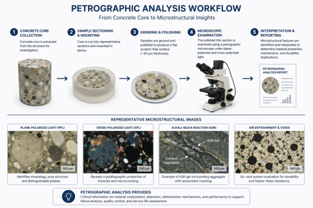
Analytical Techniques Supporting Petrography:
Capability | What It Adds |
Optical / Petrographic Microscopy | Uses transmitted and polarized light microscopy to identify phases, cracks, pores, air-voids, and microstructural relationships in prepared sections. |
Sample Preparation (Thin Section / Polished Mount) | Produces representative cross-sections (~30 µm) for accurate microstructural interpretation |
Image Analysis | Quantifies porosity, crack density, air-void parameters, and feature size distributions |
SEM-EDS | Provides high-resolution imaging and localized elemental composition of reaction products and interfaces |
XRD | Confirms crystalline phase identity (e.g., portlandite, quartz, ettringite) |
Thermogravimetric Analysis (TGA) | Quantifies mass loss associated with dehydration and decomposition (e.g., bound water, carbonates) to support phase identification and degradation analysis. |
Ion Analysis / Wet Chemistry (IC, ICP as needed) | Quantifies soluble species (Cl⁻, SO₄²⁻, Na⁺, K⁺, Ca²⁺, Mg²⁺, carbonates (CO₃²⁻ / HCO₃⁻), and alkalinity) that drive degradation, with ICP-based analysis used where total elemental composition is required. |
Mechanical Testing (Optional) | Correlates microstructural damage with strength and durability performance |
Key Differentiators
Petrographic analysis enables direct visualization of structural deterioration mechanisms. It is particularly effective for infrastructure materials, where features such as cracking, spalling, and reaction products must be evaluated in relation to the overall material structure. Petrography connects what the material contains with how the structure is arranged, how damage develops, and how those observations explain real-world performance.
Strengths
- Direct observation of cracks, voids, and microstructural defects
- Excellent root-cause capability for cracking, spalling, scaling, fire damage, and chemical attack.
- Strong fit for concrete, mineralogical, refractory, and ceramic investigations where texture and feature relationships matter.
- Can guide whether repair, replacement, or additional testing is the better next step.
- Works as the interpretive center of a broader failure-analysis program.
Limitations
- Interpretation quality depends heavily on analyst expertise and representative sampling.
- Not all chemical questions can be resolved by microscopy alone, so complementary chemistry or other techniques may still be required.
- Small or subtle features may require SEM or other higher-resolution methods for confirmation.
- The method is primarily local and observational, so non-representative samples can lead to misleading conclusions.
- Sample preparation can take significant amounts of time when thin sections, polished mounts, or multiple locations are needed.
Example Outputs
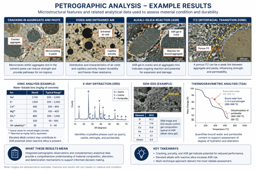
Petrographic analysis results are presented as annotated micrographs and detailed reports describing material composition and condition. Outputs include identification of cracks, voids, porosity, and reaction products such as ASR gel, along with qualitative or semi-quantitative assessments of phase distribution. Supporting analytical data (e.g., ion analysis, XRD, or thermal analysis such as TGA) may be included to correlate microstructural observations with chemical and physical degradation mechanisms.
Sample Requirements
- Provide the most representative sample possible, including both damaged and unaffected reference material when available.
- For concrete or stone investigations, note sample orientation and exact location in the structure so crack direction, exposure face, and damage depth can be interpreted correctly.
- Core sections, cut blocks, fragments containing the damaged region, or prepared coupons are all acceptable depending on the question; larger samples are generally better than undersized fragments.
- If multiple conditions exist, submit separate labeled samples rather than mixing them together.
- Avoid contaminating surfaces with oils, coatings, tape residue, or field-applied fillers before consulting on sample handling.
- Include service history, environment, temperature or chemical exposure, age, and known failure symptoms with the submission.
- If compression, chemistry, air-void analysis, XRD, SEM/EDS, or ion testing may also be needed, indicate that at intake so representative allocation can be planned from the start.
- Concrete cores and fragile samples must be well padded and immobilized during shipping to prevent fracture or edge damage, as transit-induced cracking can obscure original failure features and lead to misleading conclusions.
Petrographic Analysis Applications by Industry
Civil Infrastructure
Identify the cause of cracking, spalling, scaling, freeze-thaw damage, chloride-related deterioration, or durability loss in concrete structures, dams, bridges, piers, and containment systems.
Construction Materials
Assess aggregates, stone, and hardened concrete for deleterious constituents, entrained air condition, chemical attack, and suitability for continued service.
Refractories
Determine whether lining failure is linked to slag attack, thermal cycling, phase change, porosity evolution, or installation-related defects.
Ceramics
Examine phase distribution, porosity, inclusions, thermal damage, and fracture origin in structural or functional ceramic components.
Energy and Utilities
Investigate degradation in support structures, high-temperature systems, or chemically exposed mineral-based materials.
Mining and Geology
Classify mineral-bearing samples, evaluate textural relationships, and support mineralogical interpretation with microscopy
Failure Analysis Programs
Correlate microscopy findings with chemistry, phase analysis, and physical testing to establish defendable root-cause conclusions.
Techniques That Complement Petrographic Analysis
Frequently Asked Questions
What can petrographic analysis tell me that bulk chemistry cannot?
It shows where features occur, how they are related, and whether damage is linked to pores, interfaces, cracks, air-void condition, reaction rims, or service-induced change rather than only providing an averaged composition.
Is petrography only for concrete?
No. It is widely used for concrete, aggregates, natural stone, refractories, ceramics, mortars, cements, and other mineral-bearing materials.
Can petrography identify ASR or sulfate attack by itself?
It can often show strong visual evidence of these mechanisms, but confidence is often improved by pairing microscopy with SEM/EDS, XRD, FTIR, or ion chemistry.
How much sample is needed?
The minimum depends on the material and question, but enough material is required to prepare a representative section through the feature or damage zone of interest.
When should petrography be paired with other methods?
Whenever the investigation requires phase confirmation, localized chemistry, ionic species measurement, porosity quantification, or mechanical correlation beyond what microscopy alone can resolve.