
What is Nanoprobing?
Nanoprobing is an in-situ technique that uses ultra-fine probe tips to make direct electrical contact with microscopic features inside an electron microscope. By positioning probes onto specific device structures under high magnification, engineers can measure local electrical behavior—such as current–voltage (I–V) response—at the region of interest.
Unlike traditional optical probe stations, nanoprobing is performed inside an SEM or dual-beam system, allowing you to see with higher precision where the probes are landing and the landing force. This enables direct correlation between a device’s physical structure and its electrical performance while preserving the features, which is critical for advanced semiconductor failure analysis and device debugging.
In practice, nanoprobing turns the microscope from a purely imaging, spectroscopy, and crystal structure tool into a functional test platform—letting you not only find a feature or defect, but also determine how it behaves electrically in real time.
Compatible with SEM and Dual Beam Workflows
Localized Electrical Behavior
Flexible, Modular Platform
Why use Nanoprobing?
Nanoprobing adds direct electrical interaction to the same SEM workflow already used for imaging, navigation, and site-specific analysis. Instead of stopping at visual/elemental/crystallographic inspection, you can land probes on structures of interest and measure how a device behaves electrically at the nanoscale.
See, Contact, Measure
Fast Approach, Precise Landing
Stable Measurements Over Time
How Nanoprobing Works
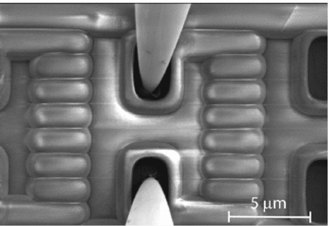
Nanoprobing operates by bringing ultra-fine conductive probe tips into direct contact with specific features on a sample inside an electron microscope. Using high-resolution SEM or dual-beam imaging for navigation, the user first locates the region of interest—such as a transistor gate, interconnect, or suspected defect site—then positions the probes with nanometer-scale precision using multi-axis manipulators. Coarse motion enables rapid positioning across the sample, while fine motion allows controlled, gentle landing of the probe tips onto targeted structures without damaging them.
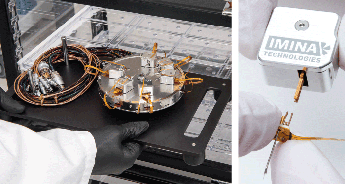
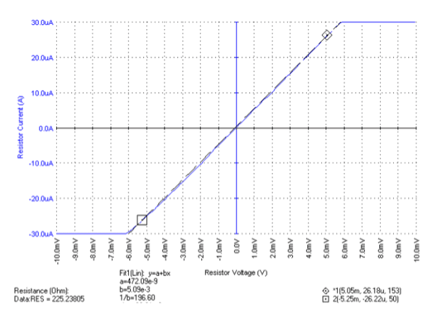
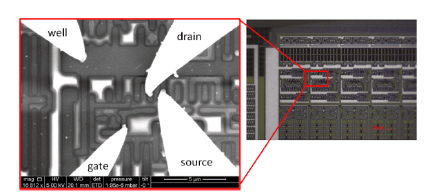
Once contact is established, electrical measurements such as current–voltage (I–V) response, resistance, or continuity can be performed in situ. Because the process occurs inside the microscope, the probe location is visually confirmed, enabling direct correlation between physical structure and electrical behavior. This integration is what distinguishes nanoprobing from traditional probe stations: instead of testing blindly at predefined pads, users can interrogate specific nanoscale features, defects, or interfaces in real time, and immediately connect what they see to how the device performs
Equipment Used for Nanoprobing
We use the Talos™ F200X G2 TEM with Super-X EDS system for DPC and other Transmission Electron Microscopy needs.

Imina NANO
Platform type: integrated into our JEOL FIB SEM.
Core motion concept: Compact mobile nanoprobers with independent multi-axis control
Degrees of freedom: 4 degrees of freedom per nanoprober
Probe count: 4
Positioning resolution: Nanometer-scale fine positioning
Coarse motion range: Up to centimeter-scale travel for rapid approach to the region of interest
Fine motion range: Up to ~15 µm at the probe tip for precise contact landing
Working conditions: Compatible with short working distances, low accelerating voltage imaging, and high-resolution magnetic-lens imaging conditions
Tilt compatibility: Supports tilt-compatible workflows, with stable contact maintained at angles used for FIB operations
Probe tips: Industry-standard tungsten probe tips, with very fine tip-radius options
Software: Integrated control software for probe positioning, measurement setup, workflow guidance, data handling, and reporting
Key Differentiators
TXRF is a technique distinguished by its exceptional surface sensitivity, ultra-trace detection limits, and non-destructive measurement, but it also has key technical constraints.
Strengths
- Direct electrical testing at the site of interest
- Real-time correlation between structure and electrical behavior
- Nanometer-scale probe placement for localized measurements
- Compatible with SEM and dual-beam workflows
- Useful for films, particles, transistors, interconnects, defects, and failure-analysis studies
- Stable contact for extended in-situ electrical measurements
- Flexible platform for a wide range of microelectronic and research devices
Limitations
- Stable contact can be difficult on very small, oxidized, contaminated, or highly topographic features
- Better suited for targeted analysis than high-throughput production testing
- Requires exposed or accessible structures for reliable probe landing
- Measurement quality depends heavily on sample condition, geometry, and operator setup
- Often most effective when combined with correlative imaging or cross-sectioning workflows
Example Outputs
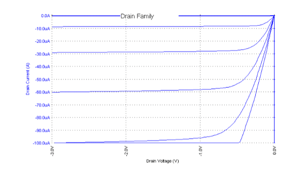
Sample Requirements
Measurement success depends on surface and sample preparation. We can help with sample preparation.
- Solid phase.
- Must be vacuum stable.
- Maximum Sample Height: 55 mm.
- Maximum Sample Weight: 500 g (including sample-holder).
- Maximum Lateral Dimension: 150 mm (larger samples enabled with reduced rotation).
Nanoprobing Applications by Industry
Semiconductor Failure Analysis
Nanoprobing is used to electrically interrogate localized areas of a failing device, helping connect electrical behavior to the physical site under investigation.
Device Characterization and Debug
Supports in-situ I–V measurements on microelectronic structures to evaluate local device behavior and compare suspect vs. nominal regions.
FIB Delayering to Probe Buried Structures
Delayer the sample and probe exposed surfaces in one tool.
Research Materials and Micro/Nanodevices
Nanoprobing can also be used for localized testing of MEMS, sensors, nanowires, thin films, nanoparticles, graphene, microLEDs, solar cells, and other research-scale devices where direct electrical access under the microscope is valuable.
Correlative Probing with FIB or SEM Review
Combine imaging, probing, and follow-on analysis such as FIB cross-sectioning for deeper root-cause investigation.
Thin Film 4 Point Probe
Investigate sheet resistance in thin films.
Techniques That Complement Nanoindentation
AFM scans a sharp probe to map nanoscale topography and material properties with sub‑nanometer sensitivity.
XPS measures surface elemental composition and chemical states within ~7–10 nm, enabling angle-resolved and depth profiling.