
What is DPC?
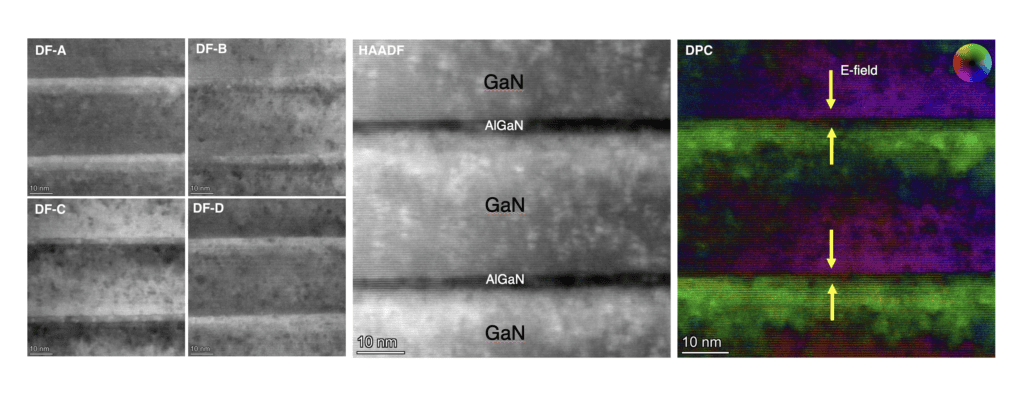
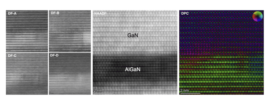
Differential Phase Contrast (DPC) is a technique that maps internal electric or magnetic fields by measuring subtle beam deflections as the electron probe scans across a sample, using a segmented detector to quantify direction and magnitude.
Why use DPC?
DPC reveals how local charge, polarization, and fields behave at the nanoscale—providing direct insight into functional properties that cannot be inferred from structure alone.
Direct electric field mapping
Sensitive to charge and polarization
Structure-to-function insight
How Differential Phase Contrast Measurement Works
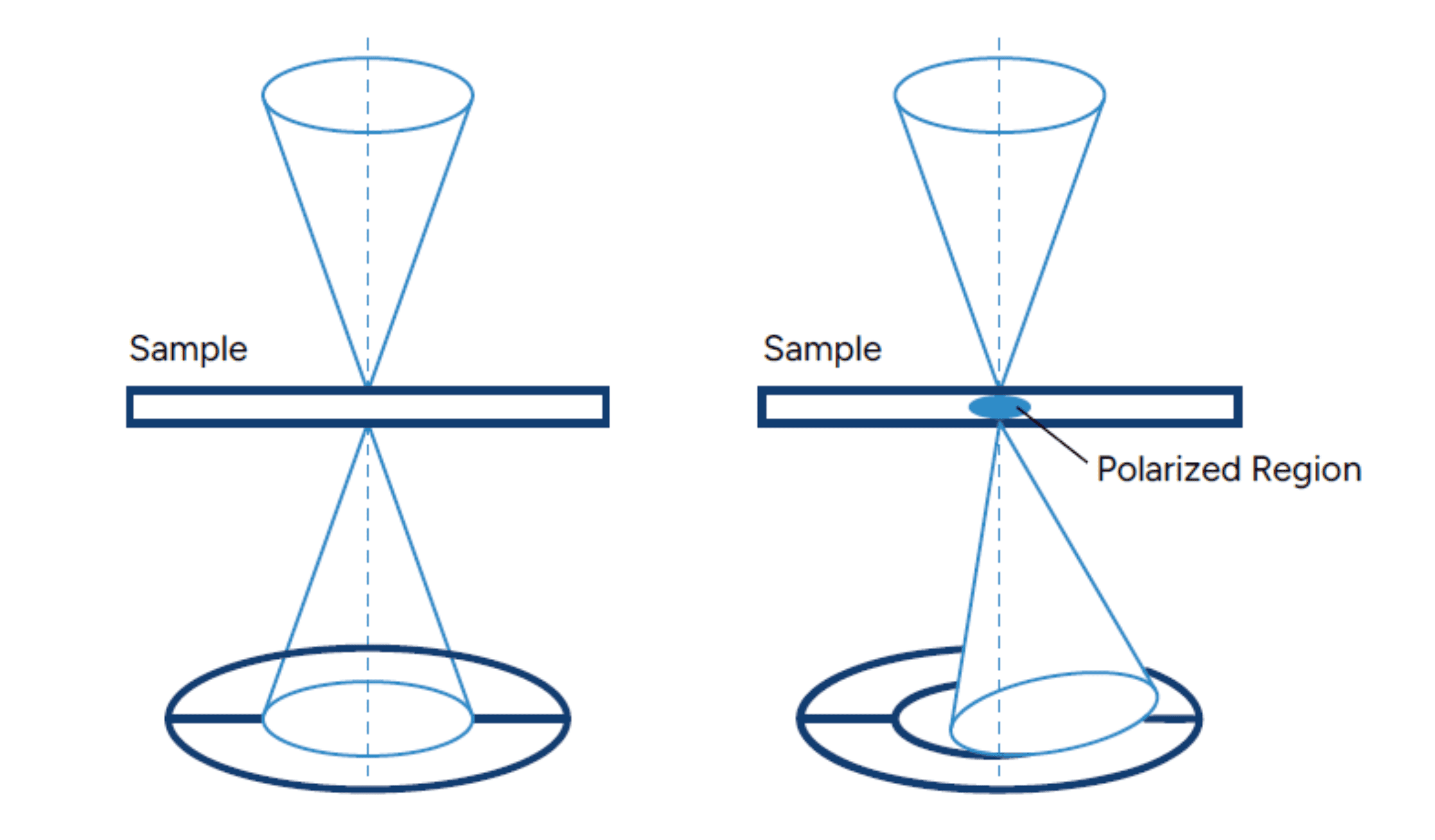
DPC uses a segmented detector located underneath the sample to measure the beam deflection at each pixel. Areas of the sample that are electrically polarized will deflect the beam and intensity differences are then converted into field direction and relative strength maps.
Equipment Used for DPC
We use the Talos™ F200X G2 TEM with Super-X EDS system for DPC and other Transmission Electron Microscopy needs.

ThermoFisher Scientific Talos F200X G2 TEM/STEM
- Electron Source: X-CFEG (High-Brightness Field Emission Gun)
- Accelerating Voltage: 200 kV
- TEM Point Resolution: ≤0.10 nm
- STEM Resolution: ≤0.16 nm
- EDS System: Super-X with 4 SDD detectors for fast 2D/3D elemental mapping
- EELS Energy Resolution: ≤0.3 eV (X-CFEG)
- Camera: Gatan OneView CCD, 16MP / 4K
- Maximum Tilt Angle: ±35° alpha / ±30° beta (double tilt holder)
- Maximum Diffraction Angle: 24°
- Software: Velox (automated workflows and large-area analysis)
Example Outputs
Sample Requirements
- Vacuum stable bulk samples, either conductive for FIB-based lamella preparation or samples can be coated with metal onsite at Covalent to mitigate charge artifacts during prep.
- OR, if you’d like to prep the samples yourself:
- Thin, electron-transparent lamella with a thickness of less than about 100nm.